PART A1
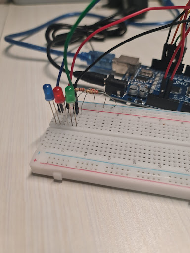
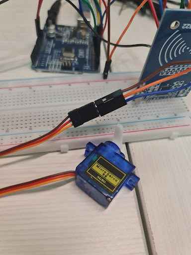
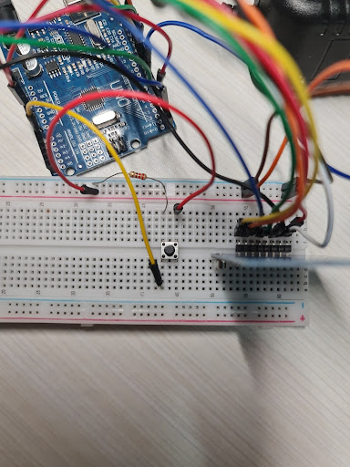
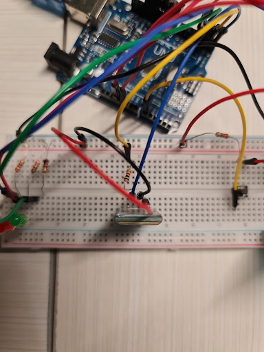
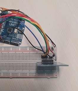
Follow the schematic below to build the RFID circuit
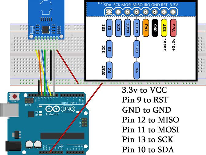
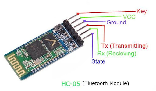
VCC = Voltage Common Collector
RST = Reset
GND = Ground (negative terminal)
MISO = Master IN Slave OUT
MOSI = Master OUT Slave IN
SCK = Serial Clock
SDA = Serial Data
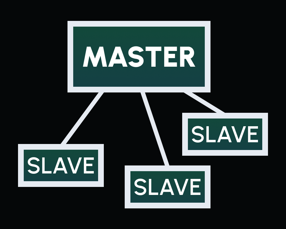
WHAT IS MASTER AND SLAVE?
Used for SPI (Serial Peripheral Interface) between a master and slaves. The master (our rfid reader), as the name suggests, controls the slave devices (our rfid tags) and serves as their communication hub
BUT... DOES IT WORK?
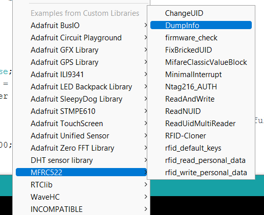
Opening up the ARDUINO IDE and installing a special package for our RFID module, we can load in a sketch named DumpInfo.
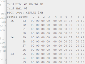
Upload this sketch to our ARDUINO and scan a card. If it shows a hex dump, congrats!
PART B
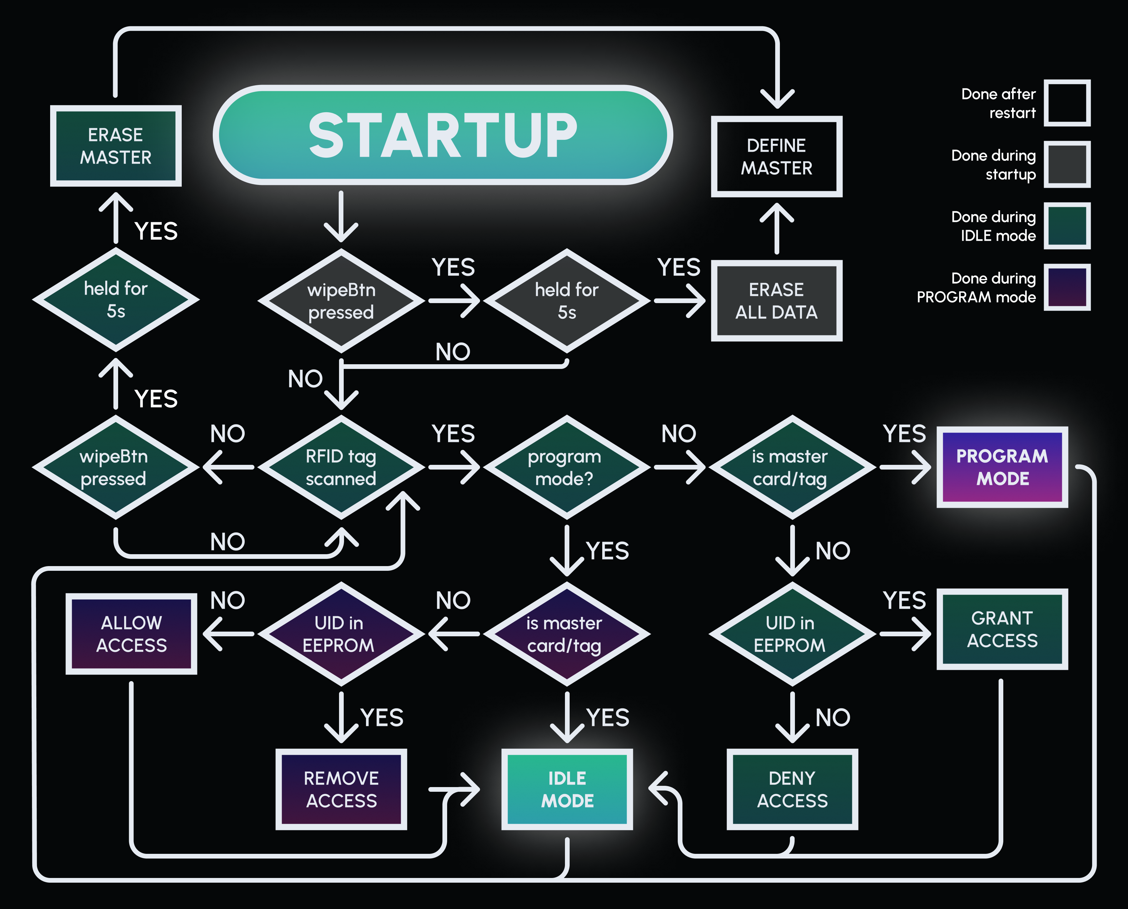
Next, code a program in the ARDUINO IDE to upload to our ARDUINO. The finished code is found here. The code should ask for a tag to be scanned (which will be the master tag) on the first run
The following is a flowchart explaining what else the code does
PART C2
Before getting to the actual app, we should test the functionality of our module. This section will lead to an app that Turns an LED on and off
CREATING THE APP
First, create an application in MIT app inventor, such as the image below. The names given are important to programming the components, so it's best to follow:
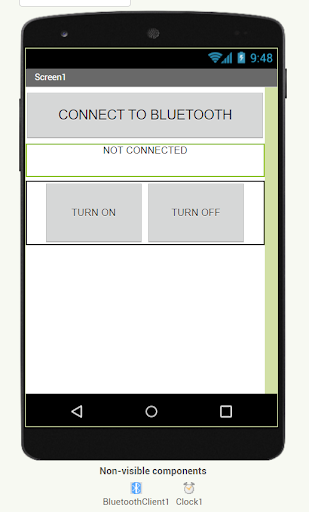
btChooseText: "CONNECT TO BLUETOOTH" list picker, will show a list of bluetooth devices to connect to when clicked
connectedStateText: "NOT CONNECTED" text label, will indicate whether the device is connected to a bluetooth device
onBtn, offBtn: "TURN ON" and "TURN OFF" buttons respectively, will be clicked to switch the LED
BluetoothClient1: will help the application connect with the bluetooth module
Clock1: will execute certain blocks every 1s
Head over to the BLOCKS tab and add the following (explanations below):
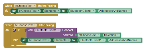
TOP BLOCK: btChooseText will show a list of available bt devices to connect to when clicked
BOTTOM BLOCK: The app will connect to a device when its name is clicked on
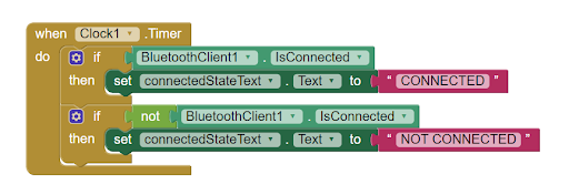
This block will change connectedStateText to show "CONNECTED" if the app is connected to a bt device, and "NOT CONNECTED" otherwise
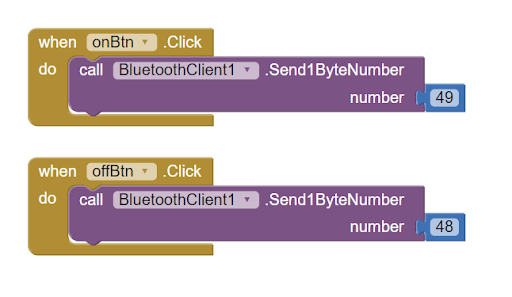
These blocks will send the number "1" (decimal 49 in ASCII) when onBtn is clicked, and the number "0" (decimal 48 in ASCII) when offBtn is clicked
ARDUINO IDE
In the arduino IDE, comment out the whole code and add in this code. This will turn on the red LED at pin 4 (refer to Step A2) if it receives a 1 from the BT module, and turns it off if it receives a 0
PART C3
Now the actual application will be made. Note that the edited ARDUINO code will be shown AT THE END OF C3
The following subparts will build up the application:
C3.0
Prepare the application and arduino code and reverse certain changes from C2 for C3.1 and beyond
Each of the following features will have state values that will be sent from the app to the BT module representing different settings and requests. The idle state value is 0
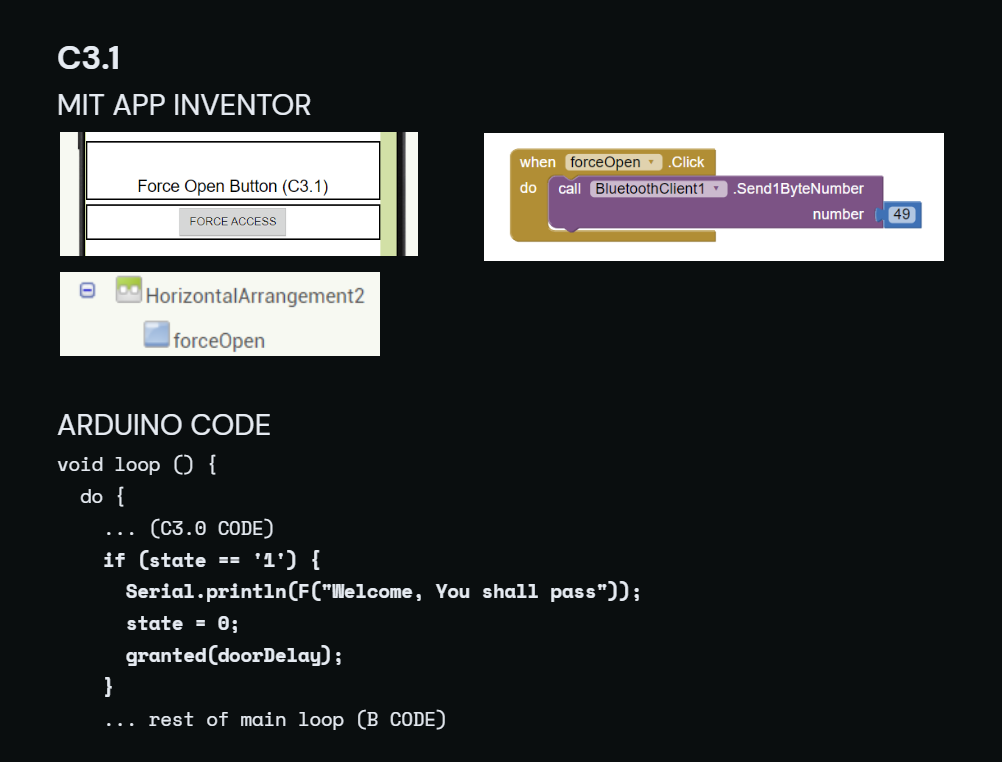
C3.1
Force the lock open even without a key. A state value of 1 will force access
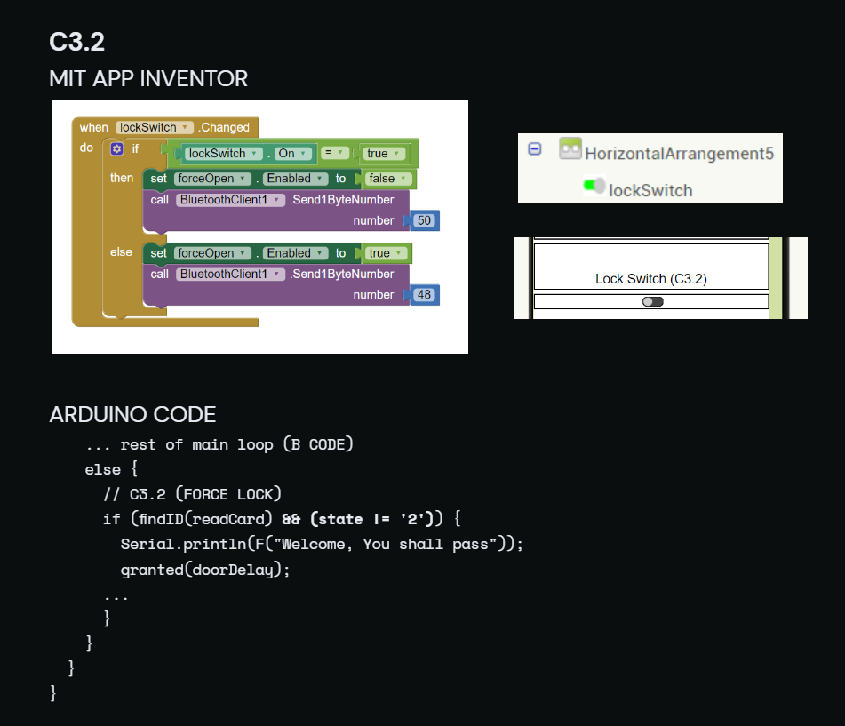
C3.2
Force the lock closed even with valid UIDs scanned. A state value of 2 will keep the lock closed
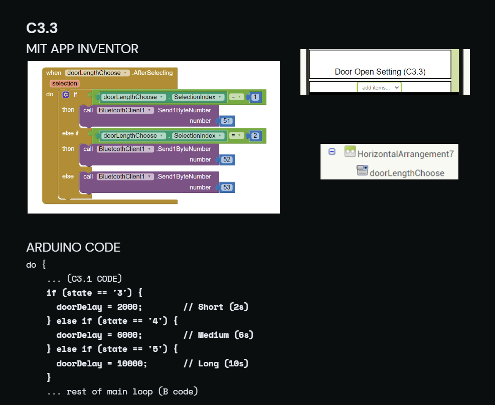
C3.3
Let the user choose from a selection of 3 lengths which the lock stays open after access is granted. State 3: 2s, state 4: 6s, state 5: 10s